November 18, 2022: I’ve updated the assembly manual to v1.1. The new version includes additional information and radio interface schematics.
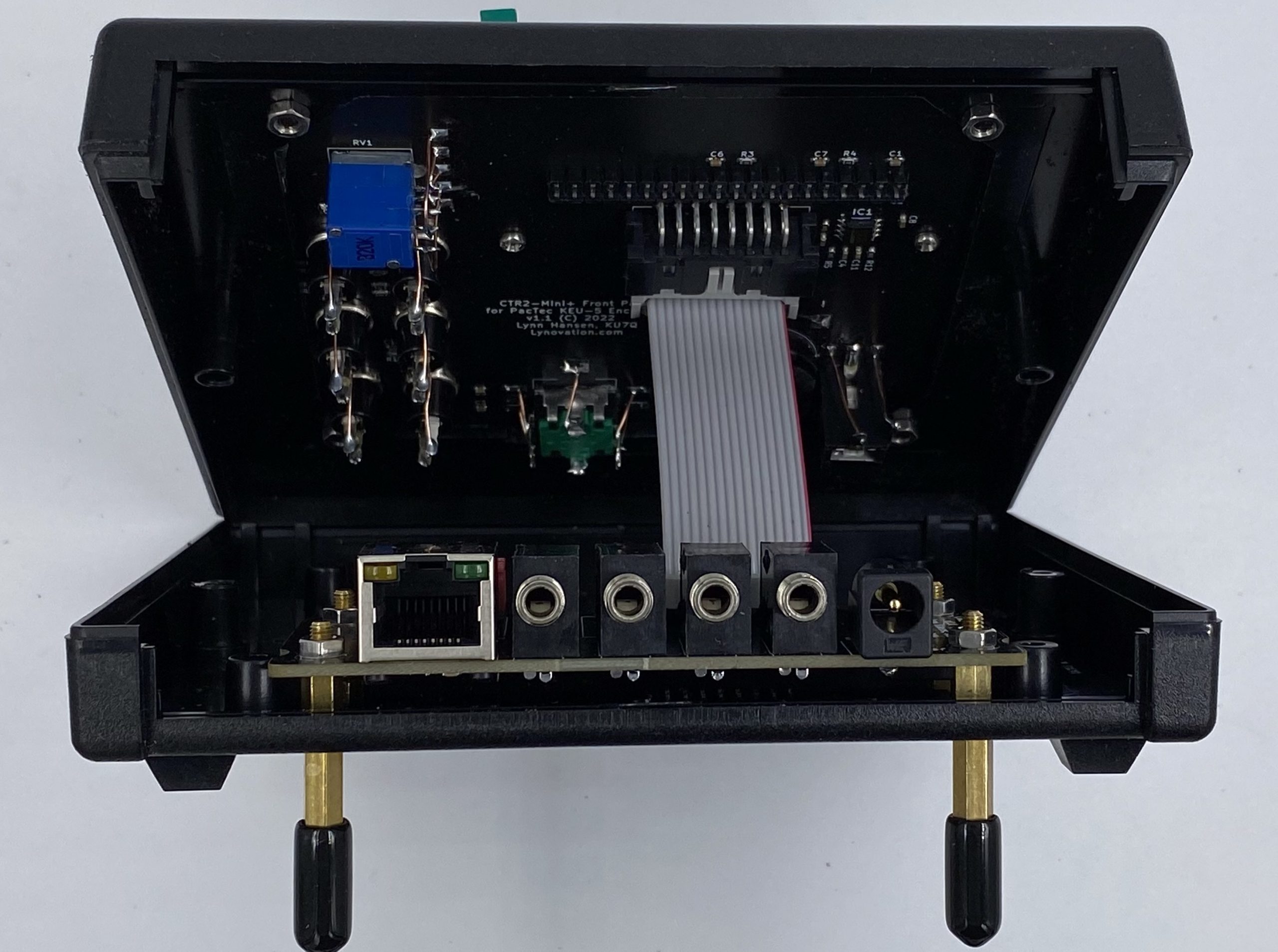
For those that want to build their own Mini+, or just want a peek under the hood at how the Mini+ is put together, download the Mini+ assembly manual below.
The Mini+ is fairly easy to build with normal hand tools. It takes about 3 hours including enclosure preparation. This should not be your first kit! While all of the SMT components and the dual-row 20-pin Wio GPIO header are pre-installed, you will need moderate soldering skills to install the headers and jacks on the boards. If you can install .1″ headers on PCBs you can build this project.
To build your own Mini+, order the Mini+ PCB kit from my order form, then order the components, Wio Terminal, and PacTec KEU-5 enclosure from the Mini+ Mouser BOM. The board kit comes with the dual-row 20-pin Wio GPIO header pre-installed and the hardware to install the boards in the KEU-5 enclosure.

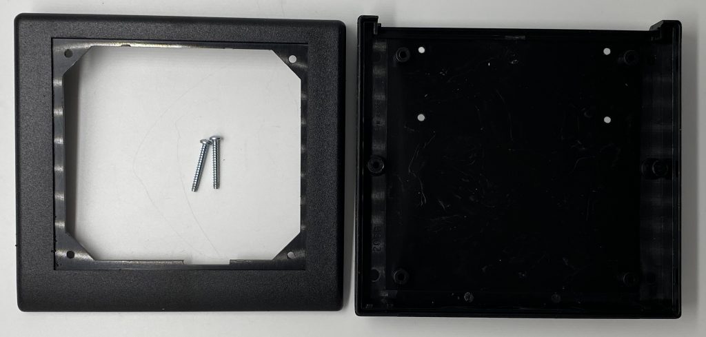
If you don’t want to do the drilling and grubbing on the KEU-5 enclosure you can order a machined KEU-5 enclosure from my order form. If you order the enclosure from me, don’t order the one on the Mouser BOM.
For those that don’t want to build their own Mini+ I offer full assembled, programmed, and tested Mini+ units on the order form.
You can also order the radio interface cables you’ll need to connect the Mini+ to your radio. You can buy the cables yourself and modify them as shown on the Radio Interface Cable page, or you can order pre-built cables for your radio from my order form.