WARNING! If you decide to build your own cables be careful about ordering cables from many vendors. They advertise that their cables are shielded. Many even claim that they have an additional foil shield for “cleaner audio”. I’ve found that the majority of the cables advertised as audio cables ARE NOT SHIELDED AT ALL. While they will work electrically you’re inviting RFI problems by using these types of cables.
The Micro has 3.5mm (1/8″) paddle, CAT, and PTT/Key. This page will provide part #s and schematics so you can purchase the cables and connectors you need to fit your radio. You can also purchase assembled cables from me on my online Shop.
The paddle jack is wired with the left paddle input on the Tip and the right paddle input on the Ring. You can reverse these in the Keyer settings in the Micro.
On the CAT I/O jack transmit data (towards the radio) is connected to the Tip, receive data (from the radio) is connected to the Ring, and ground is connected to the sleeve. The CAT signals can be configured as TTL, RS-232, or CI-V. There are two strapping options available: internal jumpers or an external DIP switch. You can select which option you want when you order your unit.
The PTT/K OUT jack has the Key output wired to the Tip of the jack and the PTT output wired to the Ring. Both signals use the Sleeve for ground.
Many radios that support the Icom CI-V interface just require a standard stereo 3.5mm cable to connect the Micro CAT I/O jack to the CI-V jack. Similarly, the CAT port on the Xiegu G90 can be directly connected to the Micro using a stereo 3.5mm cable.
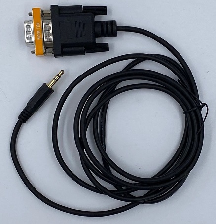
For radios like the Yaesu FTdx series with a standard DB9 RS-232 serial port you can use commercial cables with 3.5mm stereo plugs on one end and a DB9 connector on the other. Unfortunately most, if not all of the commercial cables are not wired the way the Micro’s CAT jack is, so you’ll need a null modem adapter on the DB9 end to roll the TD and RD pins.
NOTE TO KENWOOD USERS: Many Kenwood radios require either hardware or software handshaking. You can simulate hardware handshaking by jumpering pin 7 to pin 8 on the DB9 as shown on the RS232FF6 cable schematic below.
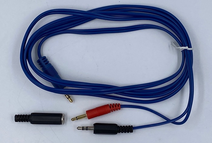
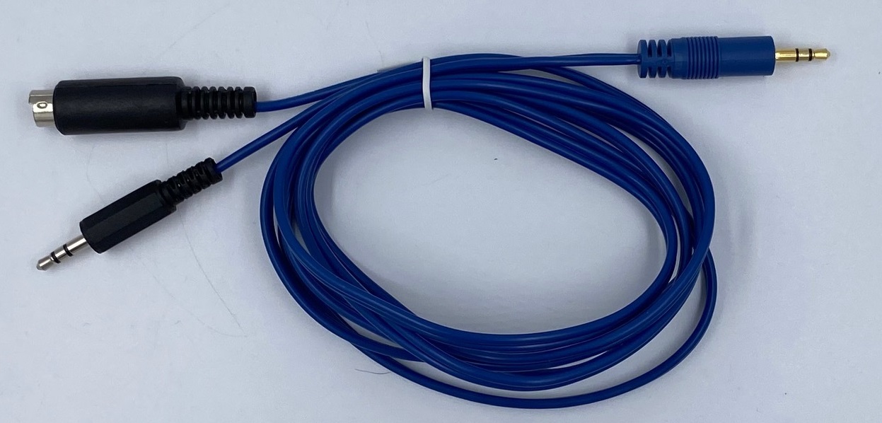
For the PTT/Key connections, a commercial 3.5mm stereo to dual 3.5mm mono splitter cable is available. I’ve found that most radios don’t like the Ring input on their Key input jack to be grounded so cut the WHITE mono plug off the splitter cable and replace it with a 3.5mm stereo plug. Just connect the single white wire in that cable to the Tip of the stereo plug and the shield to the sleeve. This leaves the Ring floating and your radio will be happy.
It seems that all radios bring PTT in through a special accessory connector. Every radio is different so I recommend wiring a 3.5mm inline mono jack (supplied with my PTTKEY6 cable) to the PTT input and ground connections on the accessory connector supplied with your radio. Plug the red mono jack on the splitter cable into this jack. If you can’t find the accessory connector for your radio, or it didn’t come with one, you’ll need to order one.
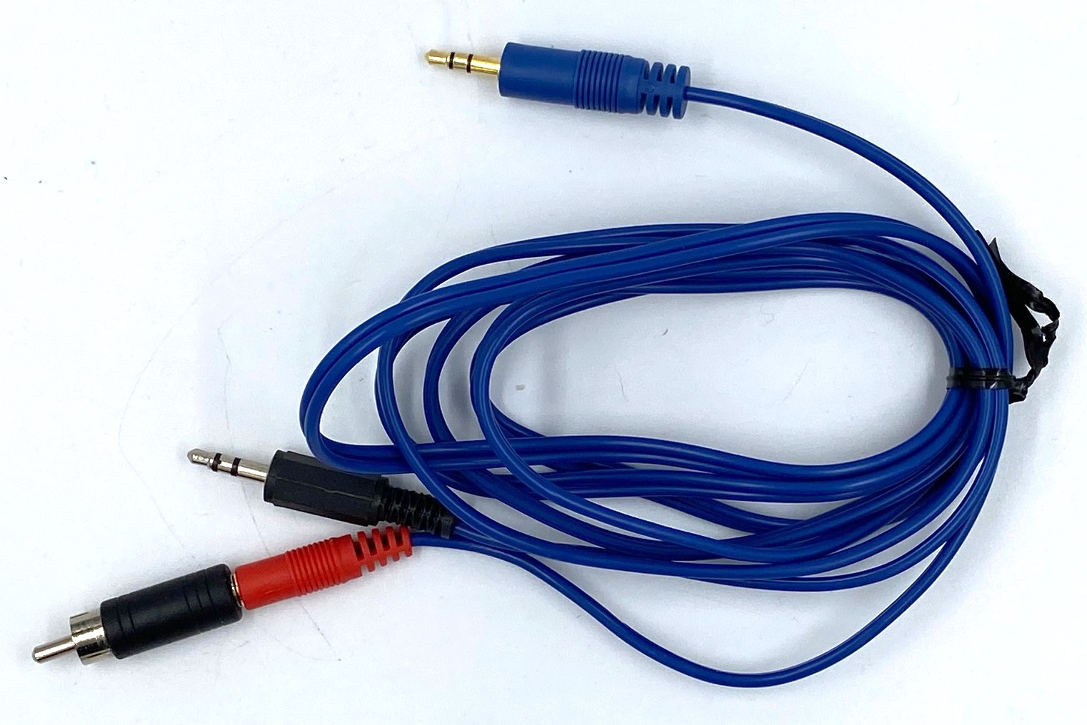
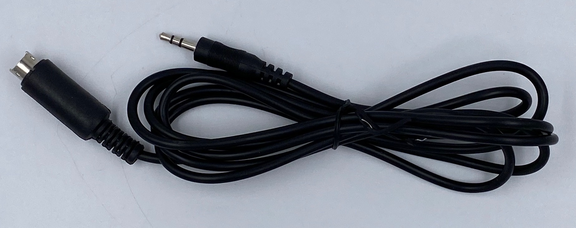
You may have an older Yaesu FT817, FT857, or FT897. In this case you can buy a commercial 3.5mm stereo cable then cut one connector off and replace it with an 8-pin mini-DIN connector, as shown in the lead photo. Be forewarned, this is not for the faint of heart. Soldering wires to the tiny pins on this connector can be a challenge.
Pre-built Cables are Available in the online Shop.
If your radio isn’t shown below it’s because I don’t have one 🙂 Send me your radio’s I/O connections and I’ll generate a schematic for it and post it here.
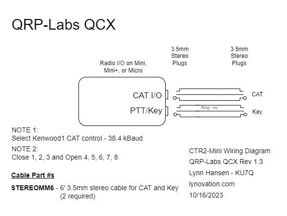
QRP-Labs QCX
Let’s start with the easiest radio to interface to, the QRP-Labs QCX. This radio only requires two 3.5mm (1/8″) stereo phone cables. Just plug them in as shown below.
Select the Kenwood1 on the Config->Radio CAT menu and select 38.4 kBaud on the Config->Radio Baud menu. Close switches/jumpers 1, 2, and 3 and open switches/jumpers 4, 5, 6, 7, and 8 on the Radio I/O module.
NOTE: Because of the simple CAT circuit in the QCX it’s best to plug the CAT and Key connections in before powering the radio up.
STEREOMM6 Cable (2 required)
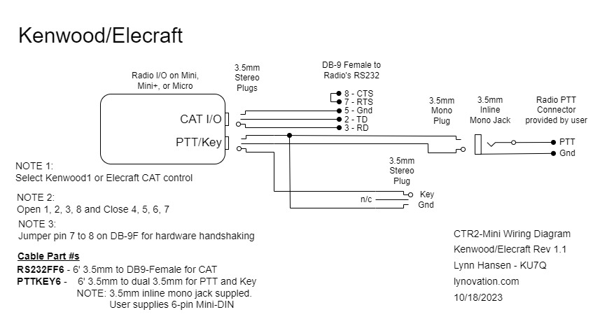
Kenwood/Elecraft
Newer Kenwood and the Elecraft radios generally have an RS-232 connector on the radio for CAT control. Older radios like the TS-680 require additional hardware to be purchased for CAT control.
You can build your own CAT cable by buying a 3.5mm stereo to DB9-M cable then adding a DB9-F to DB9-F null modem adapter to it. The null modem rolls the Tip and Ring on the stereo jack so the TD and RD signals from the radio arrive on the proper pins for the Mini or Micro.
Some Kenwood radios require hardware or software flow control. Hardware control can easily be accomplished by simply jumpering RTS to CTS (pins 7 and 8) on the DB9-F connector that plugs into the radio’s RS-232 control port. A small 30 ga. wire can be used on the null modem adapter for this purpose.
RS232FF6 and PTTKEY6 cables
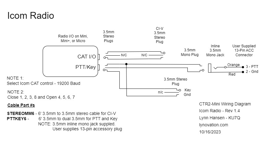
Icom Radios
If you don’t need to control PTT with the Mini or Mini+ just use two 3.5mm (1/8″) stereo phone cables to connect the Icom’s CI-V CAT and Key to the external Radio I/O module or to the Mini+. If you want to use the PTT functions of the Mini (remote PTT switch, PTT latch) use a 1/8″ stereo to dual 1/8″ mono splitter such as this one. Replace the white mono plug on the splitter with a 3.5mm stereo plug. Wire the Red and Orange leads on the 13-pin accessory plug pig-tail that came with the radio to an inline 3.5mm mono jack. Plug the red mono plug on the splitter into this jack.
Select the Icom in the Mini’s Config->Radio CAT menu. The baud defaults to 19.2 kBaud. Close switches/jumpers 1, 2, 3, and 8 and open switches/jumpers 4, 5, 6, and 7 on the Radio I/O module or Mini+ internal radio I/O header.
STEREOMM6 and PTTKEY6 cables
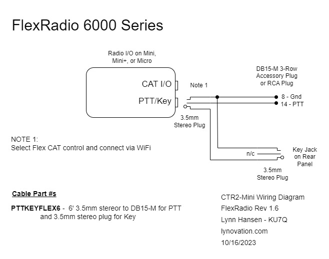
FlexRadio Series 6000
The FlexRadio 6000 Series is another easy radio to connect to because you only need to connect the Radio I/O module’s Key output (Tip and Sleeve) to the Key input on the back of the radio with a 3.5mm stereo phone cable. If you also want to control PTT on the radio, purchase a 1/8″ (3.5mm) stereo to dual 1/8″ mono adapter and a DE-15M connector. Replace the white mono plug with a 3.5mm stereo plug. Replace the red mono plug DE-15M connector. You can also use an RCA connector instead of the DE-15M. You can do away with the Radio I/O all together as the Mini and Micro can control the Flex PTT and Key over the WiFi connection.
Select Flex on the Config->Radio CAT menu. Next, in the Mini’s main menu, open the Flex 6000 menu and set the IP address of your Flex radio. The radio’s IP address can be found in SmartSDR on the Settings->Radio Setup…Network tab. Finally, connect the Mini to your local WiFi network to connect to your radio.
PTTKEYFLEX6 cable
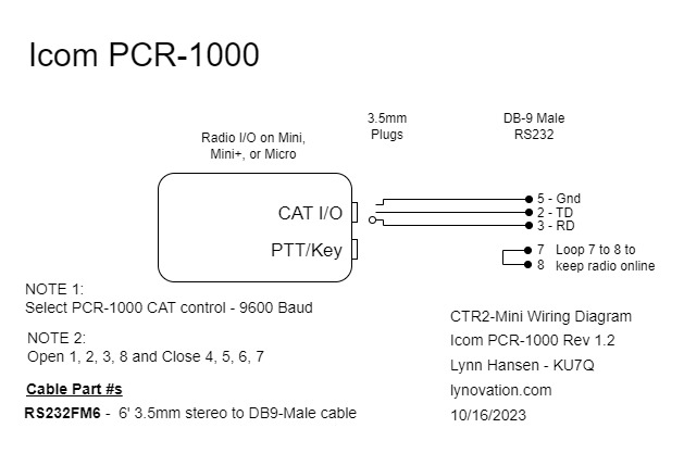
Icom PCR1000
The Icom PCR1000 receiver is also easy to connect to the Mini because it only requires a CAT connection. Buy a 3.5mm (1/8″) stereo phone jack to a DB-9 Male connector as shown below. Install a DB9 Female/Male null modem adapter on the radio side to roll the TD and RD signals. Make sure you loop pin 7 to 8 on the DB9 male connector attached to the radio otherwise the radio will shut off a few seconds after you turn it on with the Mini.
Select the PCR1000 in the Config->Radio CAT menu. The baud rate is automatically set to 9600. Open switches 1, 2, 3, and 8 and close switches 4, 5, 6 and 7 on the Radio I/O module.
RS232FM6 cable
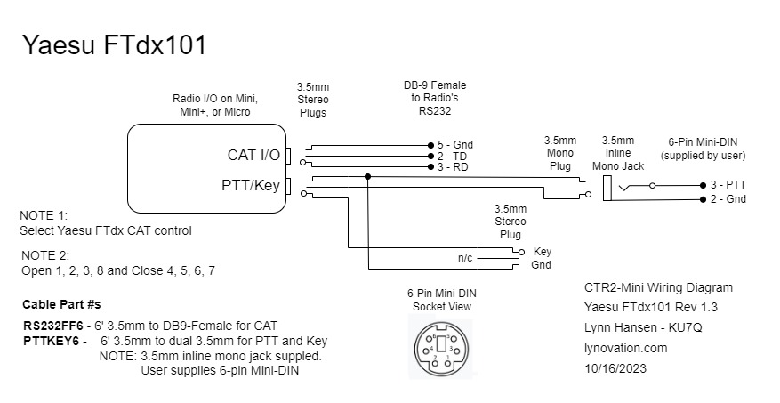
Yaesu FTdx (10, 101, and other FTdx models)
The FTdx radio series is a little more complicated to interface to because of the DB9 RS232 and 6-pin Mini-DIN connectors. One 6-pin plug is supplied with the radio. These can also be ordered from Mouser, Digikey, or several other part suppliers.
For the Key and PTT interface, purchase a 1/8″ (3.5mm) stereo to dual 1/8″ mono adapter and replace the white 3.5mm mono plug with a 3.5mm stereo plug. Connect the single wire in this cable to the Tip of the stereo plug and the shield to the sleeve. Leave the Ring terminal open. Wire a 3.5mm inline mono jack to the 6-pin Mini-DIN as shown and plug the red 3.5mm mono plug into this jack.
Purchase a 3.5mm stereo plug to DB9-Male adapter and install a DB9 Female/Female null modem adapter on the DB9 end. Plug the DB9-Female end into the RS232 DB9 connector on the back of the radio.
Select Yaesu FTdx on the Config->Radio CAT menu and set the baud in the Config->Radio Baud menu to match the baud rate set in the radio’s 232C RATE setting on the radio’s the Operation Setting->General->232C RATE menu. Open switches 1, 2, 3, and 8 and close switches 4, 5, 6 and 7 on the Radio I/O module.
NOTE: You can use both CAT ports (RS232 and USB) on the radio at the same time! This allows you to run third party apps such as logging programs and digital programs on the USB port and have all the features of the Mini or Micro on the serial port. Think of the possibilities!
RS232FF6 and PTTKEY6 cables
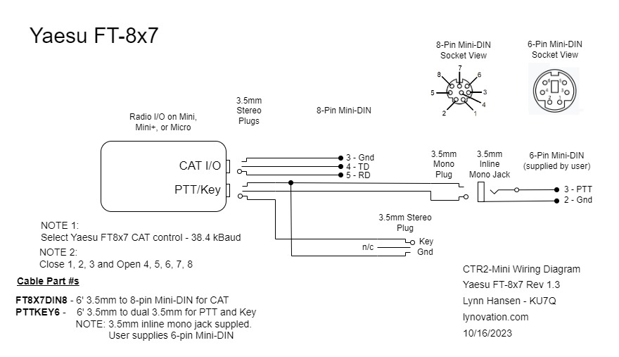
Yaesu FT-8×7
The Yaesu FT-817, FT-857, and FT-897 all use the same interface connections and are the hardest to interface to. They use a 6-pin Mini-DIN plug for PTT, an 8-pin Mini-DIN for CAT and a 1/8″ (3.5mm) stereo phone plug for the Key input.
For the CAT connection use an 8-pin mini-DIN breakout cable such as this one and just install a 3.5mm stereo plug on the wires connected to pins 3, 4, and 5 as shown below. Use heat shrink tubing on the other wires to keep them from shorting together or to ground.
For the Key and PTT interface, purchase a 1/8″ (3.5mm) stereo to dual 1/8″ mono adapter and replace the white 3.5mm mono plug with a 3.5mm stereo plug. Connect the single wire in this cable to the Tip of the stereo plug and the shield to the sleeve. Leave the Ring terminal open. Order a 6-pin mini-DIN male to male Cable for a PS/2 device similar to this one and cut one connector off. Wire a 3.5mm inline mono jack to pins 2 and 3 on the 6-pin Mini-DIN cable as shown below and plug the red 3.5mm mono plug on the splitter into this jack.
Select Yaesu FT8x7 on the Config->Radio CAT menu. The baud rate defaults to 38.4 kBaud. Close switches 1, 2, and 3 and open switches 4, 5, 6, 7, and 8 on the Radio I/O module.
FT8X7DIN8 and PTTKEY6 cables
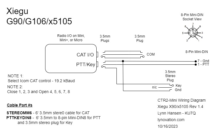
Xiegu G90, G106, and X5105
The Xiegu series radios require a 3.5mm (1/8″) to 3.5mm stereo plug for CAT (it plugs into the CAT port on the front panel of the G90), an 8-pin Mini-DIN plug for the PTT, and a 3.5mm stereo plug for the Key.
For the Key and PTT interface, purchase a 1/8″ (3.5mm) stereo to dual 1/8″ mono adapter and replace the white 3.5mm mono plug with a 3.5mm stereo plug. Connect the single wire in this cable to the Tip of the stereo plug and the shield to the sleeve. Leave the Ring terminal open. Wire a 3.5mm inline mono jack to an 8-pin Mini-DIN as shown and plug the red 3.5mm mono plug into this jack.
Select Xiegu in the Config->Radio CAT menu. The baud will default to 19.2 kBaud. Close switches 1, 2, and 3 and open switches 4, 5, 6, 7, and 8 on the Radio I/O module.
NOTE: PTT does not appear to work when connecting PTT to GND (pins 1 and 7) on the 8-pin mini-DIN ACC jack on the G106 so you can use a second STEREOMM6 cable from PTT/K OUT on the Mini or Micro to just the Key In jack on the radio.
STEREOMM6 and PTTKEYDIN8 cables